UCI Rocket Project — Liquids
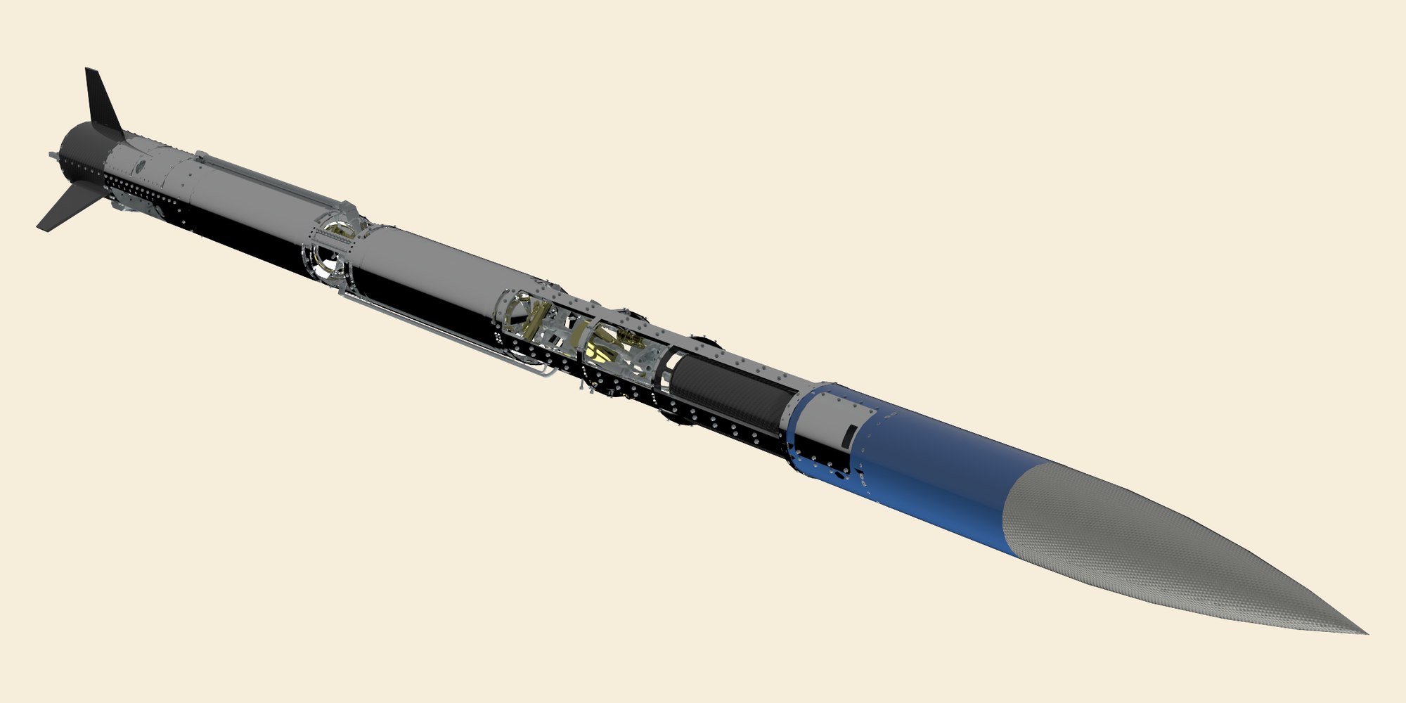
UCI Rocket Project's Liquids team is building the university's second liquid bi-propellant rocket. I joined in May 2025 as a propulsion engineer, and since March 2026 I have led the team as its Project Manager and Test Program Manager.
Project Manager & Test Program Manager
March 2026 – Present

I lead the Liquids team as its Project Manager and Test Program Manager, a role I took over in March 2026. The team is more than thirty students from across mechanical, aerospace, electrical, and software engineering, and I own its schedule against our major milestones and its budget, which runs to about $60,000 over the school year.
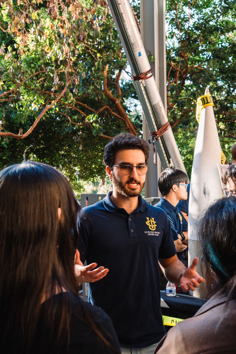
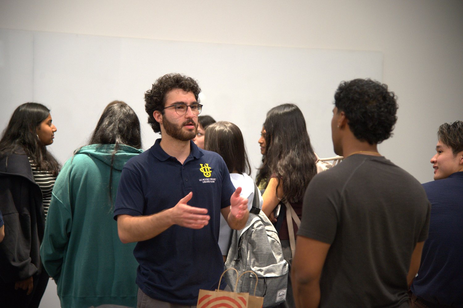
As Test Program Manager I am responsible for the logistical readiness of every test we run, from propellant cold flows and engine hot-fires to solid motor launches. I am also the team's first point of contact with the university and with our industry sponsors, and I represent the team at recruitment and outreach events.
I came onto the team as a propulsion engineer, and the four projects below were mine over the year before I stepped into leading it.
Propulsion Engineer
May 2025 – March 2026
I joined the Liquids team in May 2025 as a propulsion engineer. Over the next year I owned four parts of the propulsion and ground support system: the cascading K-bottle manifold, the feed system manifolds, a venturi flow meter, and the engine mount.
Cascading K-bottle manifold
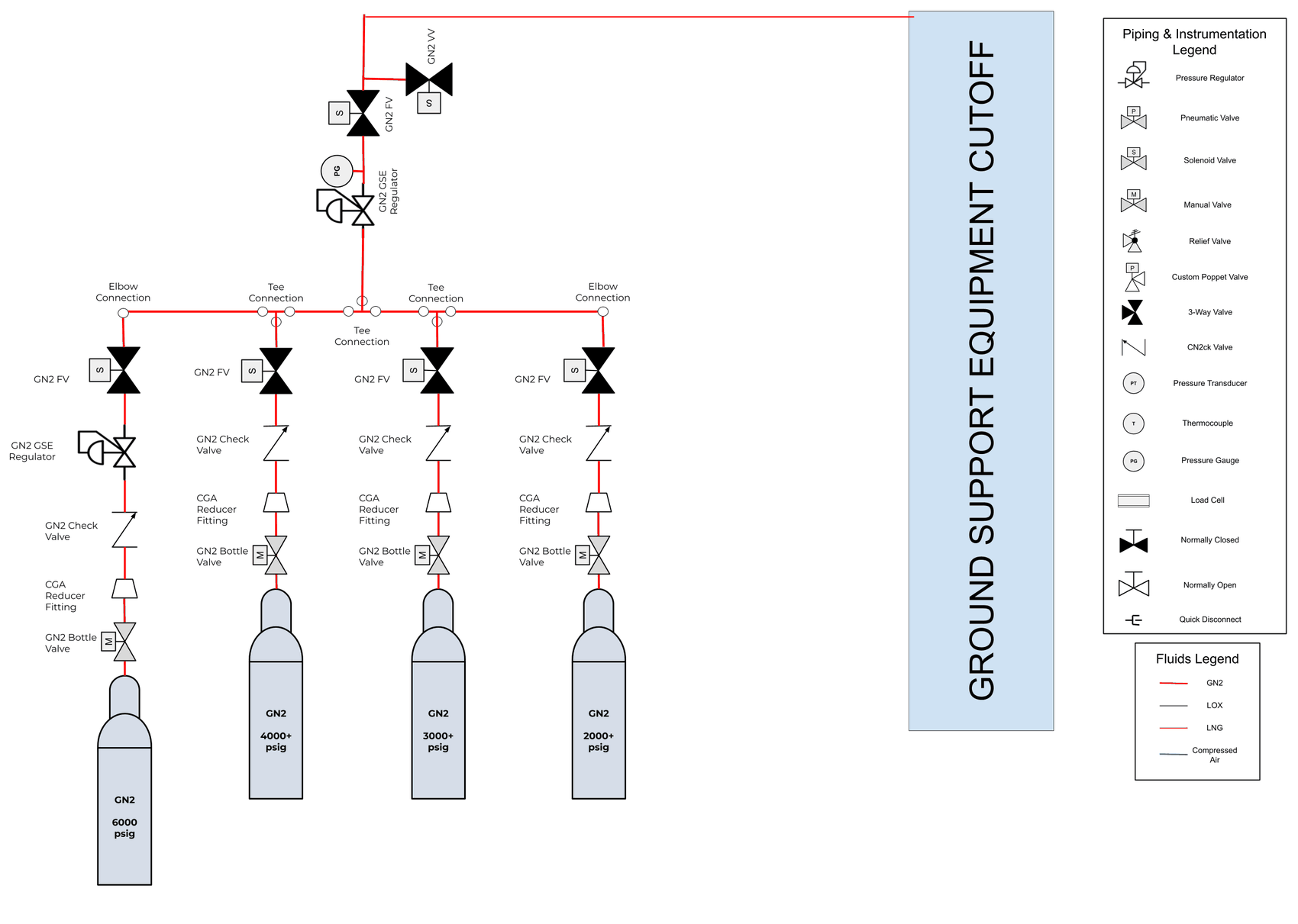
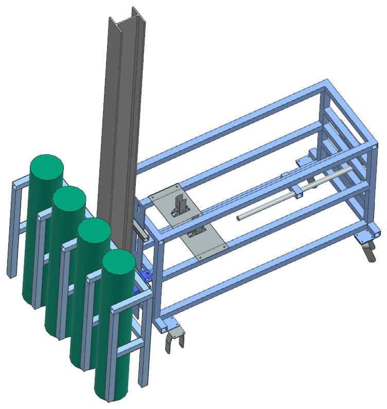
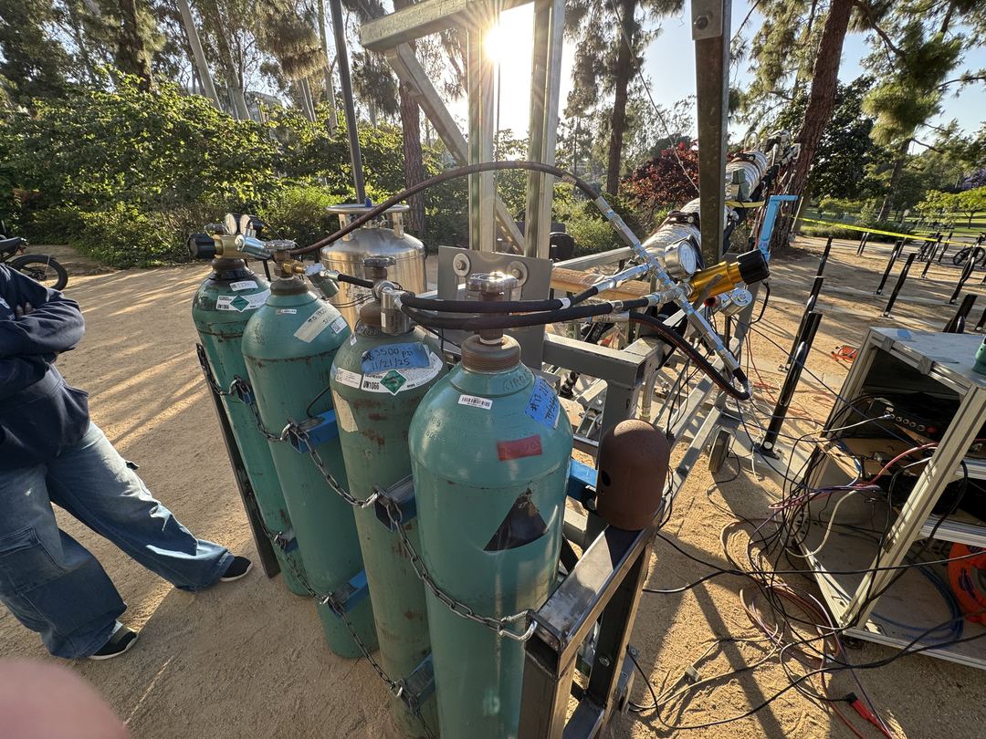
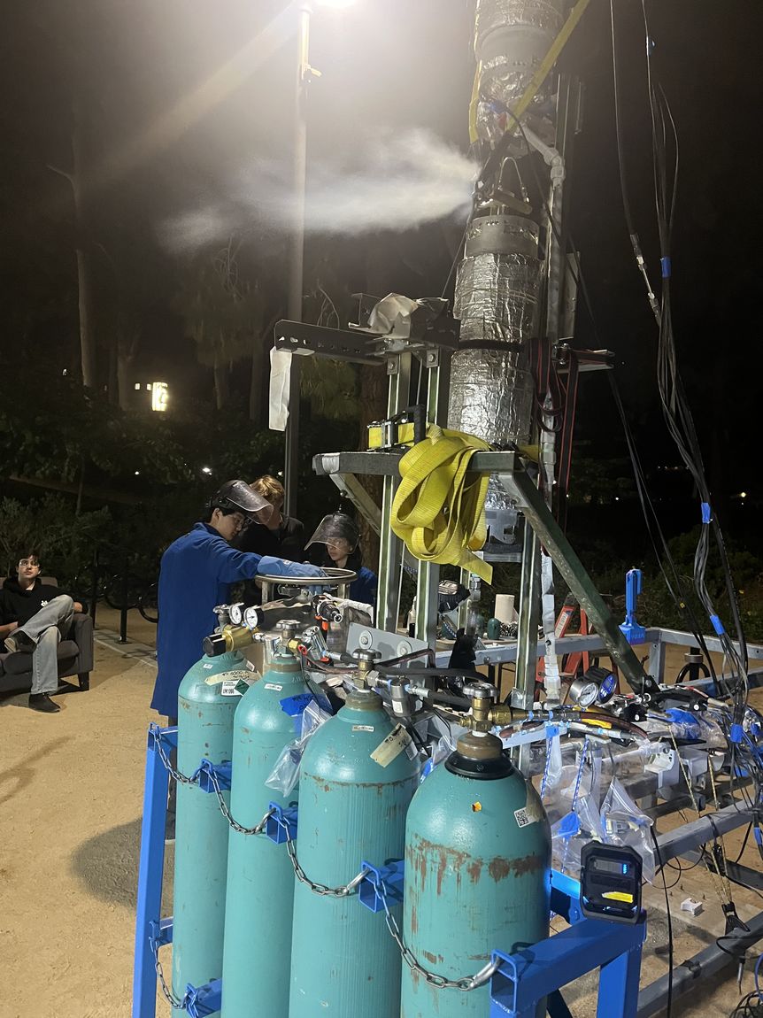
Filling a rocket's propellant tanks to flight pressure takes high-pressure gas, and running that gas from a single K-bottle empties the bottle quickly and lets its pressure sag as it drains. I designed and validated a cascading K-bottle manifold for automated tank pressurization. Four nitrogen K-bottles are staged at descending pressures, from 6,000 psi down to 2,000, and drawn down in sequence, so the manifold holds a regulated tank pressure while pulling far more usable gas from each bottle before it has to be changed out.
Automating the pressurization cut the turnaround between a cold flow and a hot-fire by 50%, opened up running two hot-fires in a single test day, and saved the team about $3,000.
Feed system manifolds
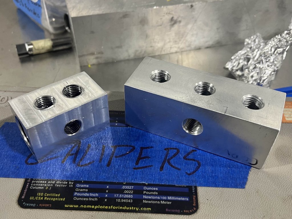
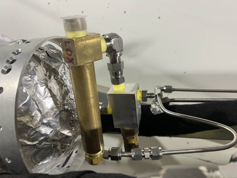
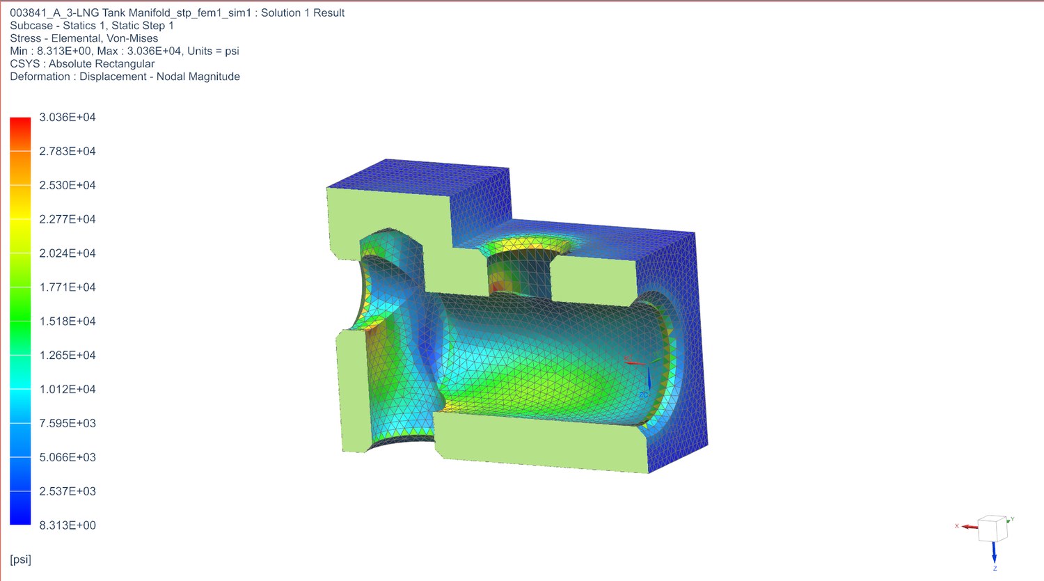
Working from designs by fellow propulsion engineer Troy Holly, I machined and tested three feed system manifolds, one each for the liquid oxygen (LOX), liquefied natural gas (LNG), and pressurant (COPV) lines. Each one consolidates a cluster of tube fittings into a single machined block, and every fitting removed is one less place the feed system can leak. Before cutting metal I ran the stress analysis on the LNG manifold to confirm the block kept margin at operating pressure, then machined all three and leak-checked them on the vehicle.
Venturi flow meter
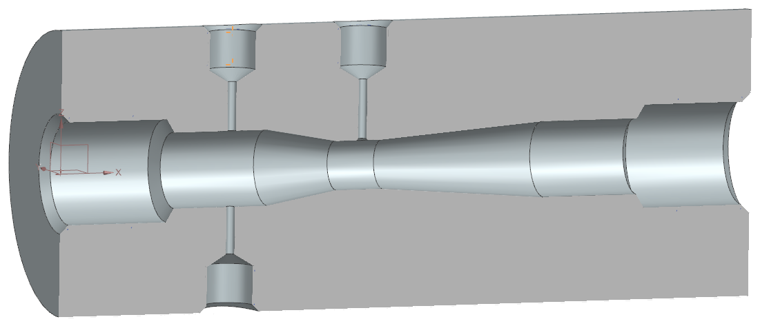
To tune the engine's injector, the team needed its discharge coefficient: the fraction of the ideal flow the injector orifices actually pass once friction and sharp edges are accounted for. Measuring the real mass flow rate through the injector and comparing it against the ideal Bernoulli prediction gives that number, and it sets how the injector inlet pressures are trimmed for a stable chamber pressure.
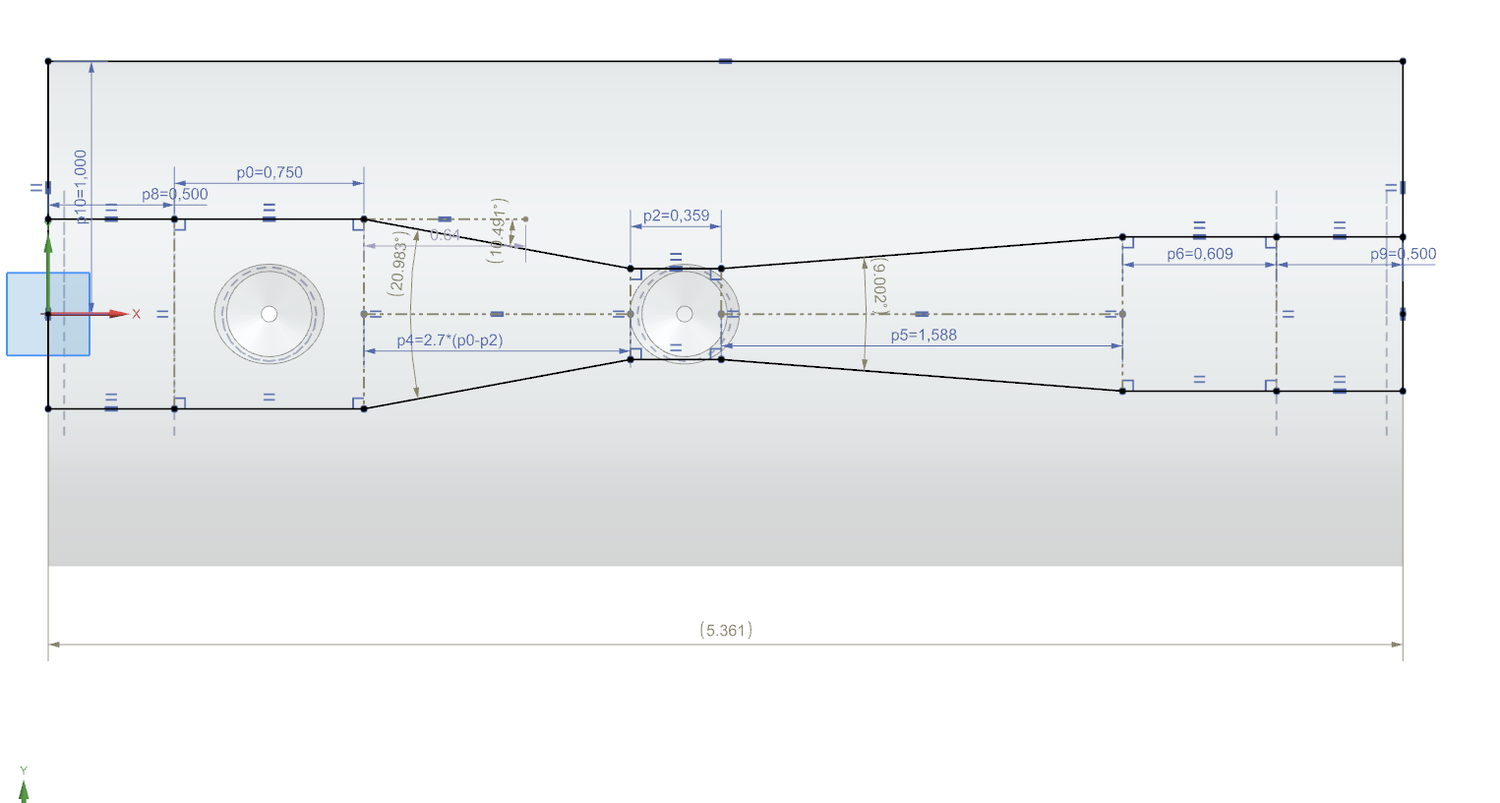
I designed a water venturi to ISO 5167-4 and made it in house. I drilled and reamed the throat to diameter and used a boring bar for the converging and diverging profiles, then tapped both pressure-transducer ports with NPT threads. The venturi was designed for a 100 psi pressure differential across the throat, and it achieved that differential during testing.
Engine mount
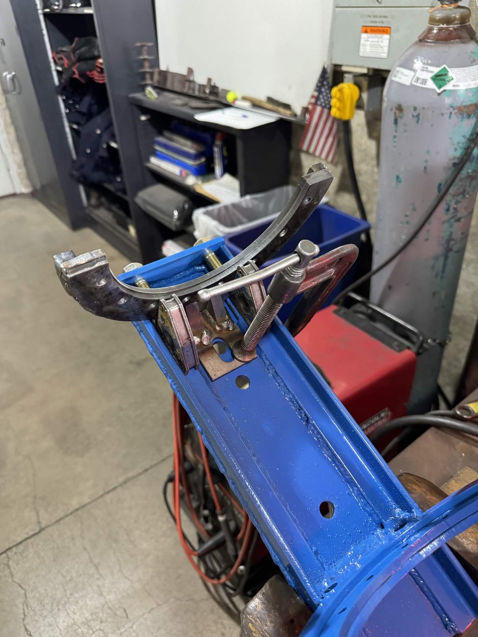
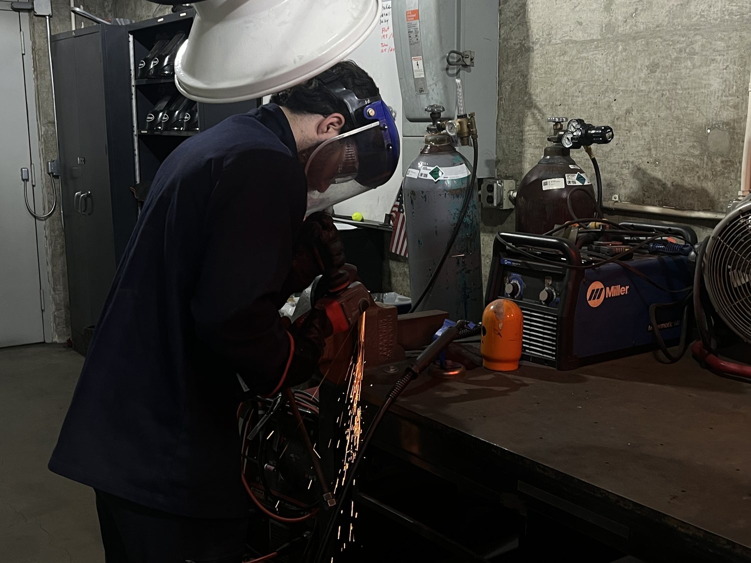
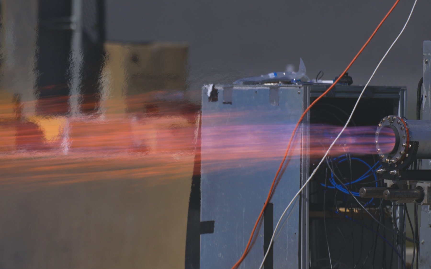
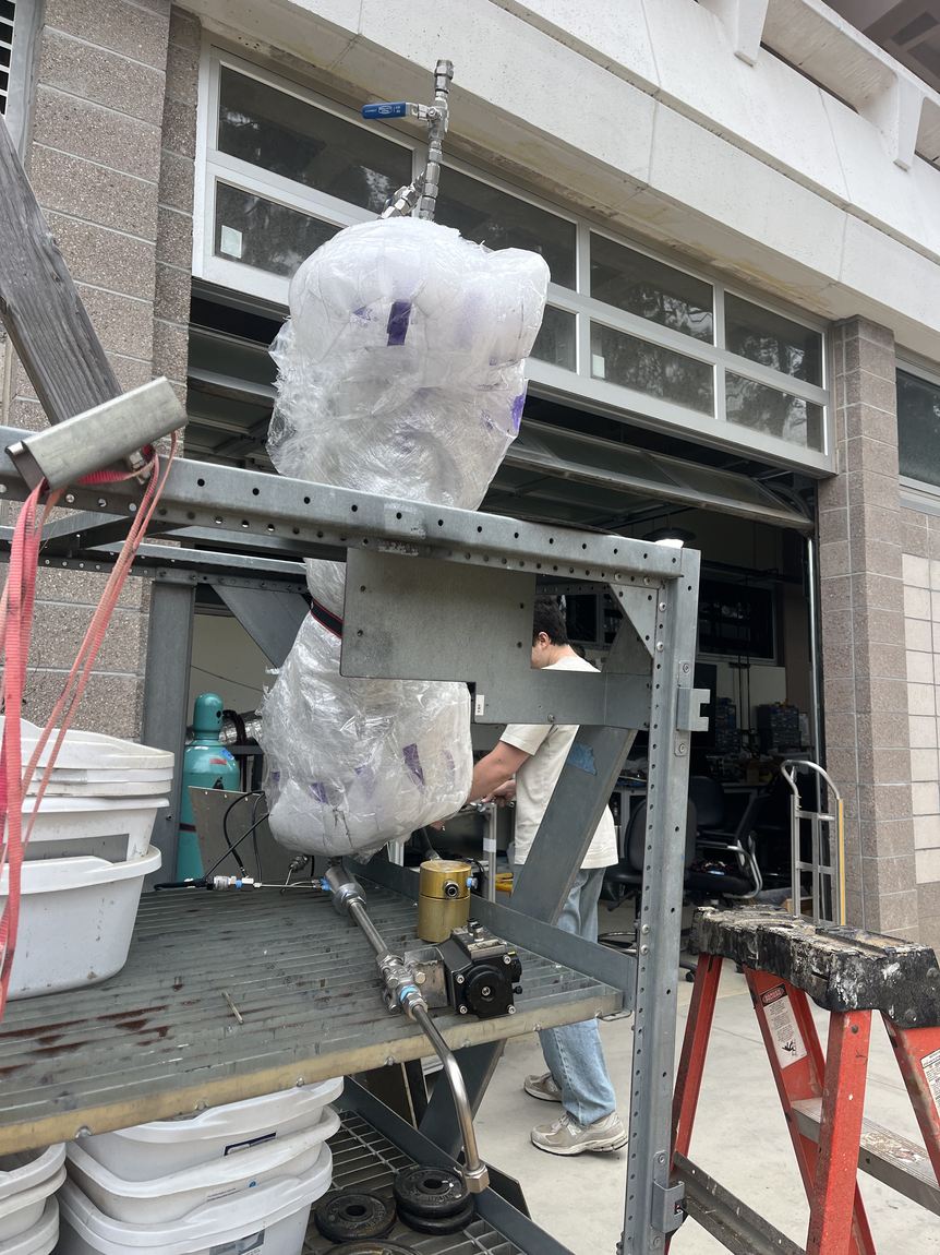
I manufactured the engine mount that carries the methalox engine on the horizontal test stand for cold flows and static hot-fires. It is a welded steel structure with a machined saddle that locates the engine and reacts its thrust into the stand. I cut and welded it in the machine shop, and it has taken the load on every cold flow and hot-fire the team has run since.