UCI Solar Car
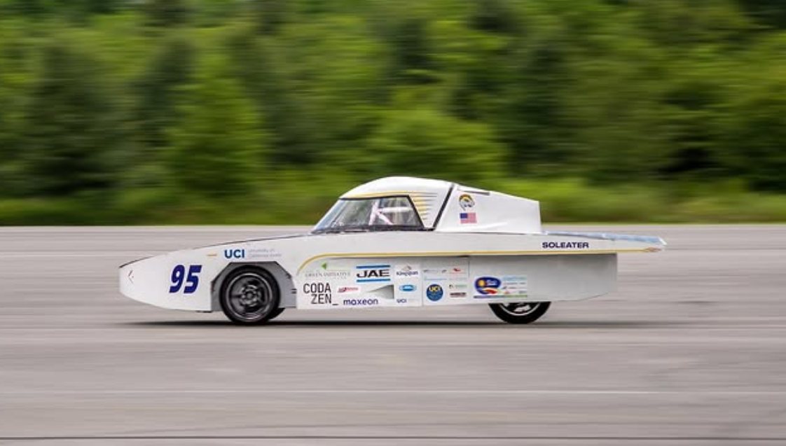
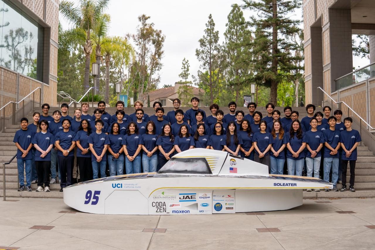
I joined UCI's solar car team (ZotSun) as a second-year student and spent two quarters on the suspension subteam, working on UCI's first ever solar car. Over that time I took the suspension from analysis and reverse-engineering through fabrication and assembly to a competition-ready rolling chassis for the Formula Sun Grand Prix.
Vehicle dynamics and load cases
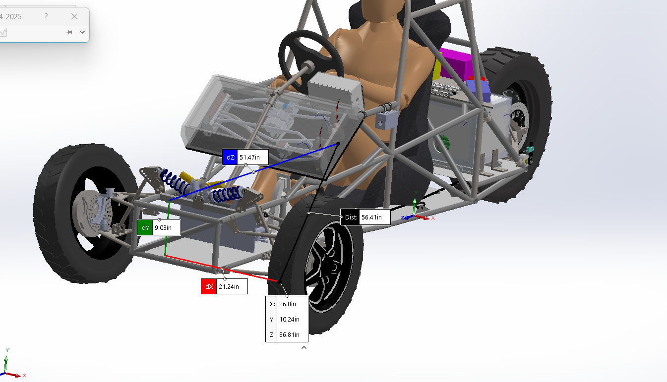
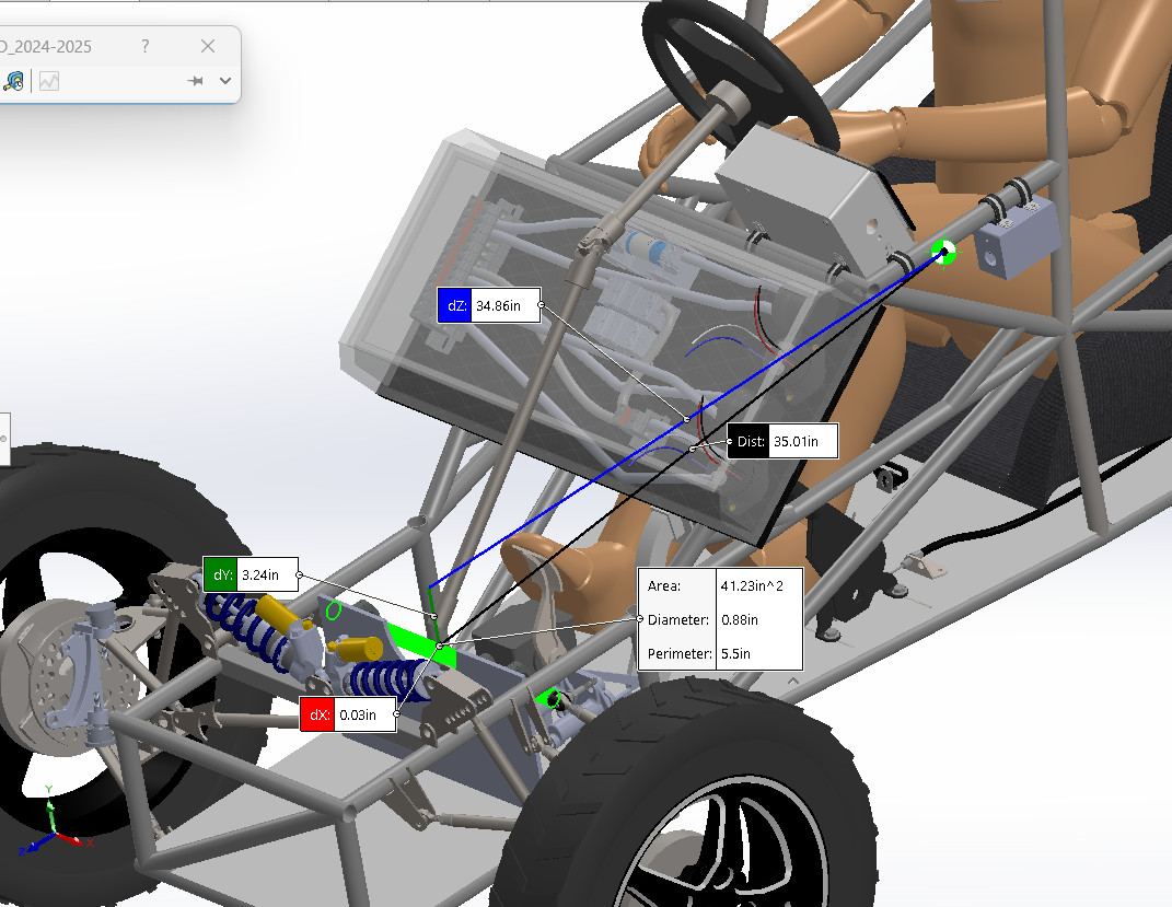
Before any of the suspension hardware could be sized, I needed the car's mass properties. Working from the master CAD assembly, I measured the height of the center of gravity, the wheelbase, the distance from the front axle to the center of gravity, and the front track width. From those I calculated the car's static tipping angle and got 35.42 degrees against a required 45 degrees, which showed that the geometry itself, not just the parts, had to change for the car to pass. That analysis also set the load cases the rest of my work was built around: a 1G cornering load, a 2G vertical bump, and a 1G braking load.
Reverse-engineering the steering upright
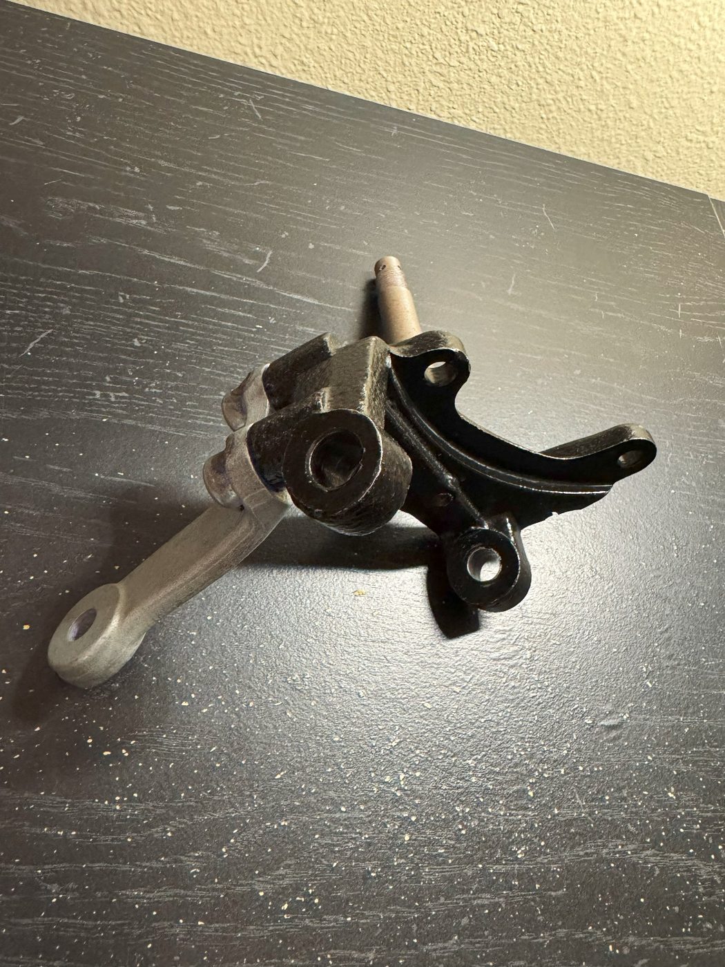
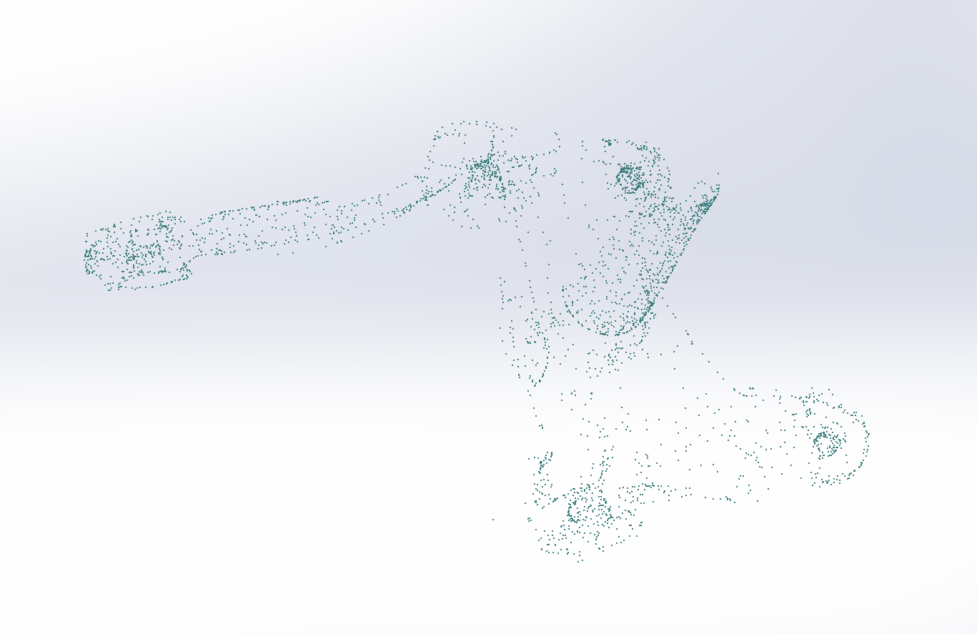
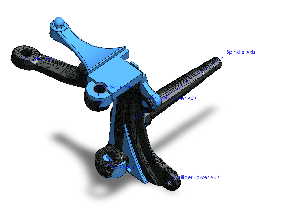
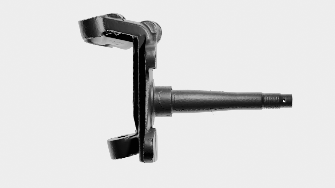
The master CAD carried only a rough placeholder for the front steering upright, the part that holds the wheel bearing, the steering arm, and the brake caliper. A rough model cannot be analyzed or manufactured, so I rebuilt it from the real part. I collected coordinate data on a CMM to generate a point cloud and a map of every hole, and had the physical upright 3D laser scanned. From the scan I built a high-fidelity, manufacturable CAD model, added the reference axes the suspension geometry is defined against (the spindle axis, the ball joint, and the lower control-arm and caliper axes), and re-integrated it into the front suspension master assembly using sketch geometry so the rest of the assembly updated around it. The accurate model made meaningful FEA and simulation possible for the first time.
Fabricating the rear trailing arm
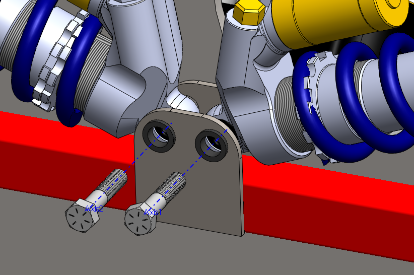
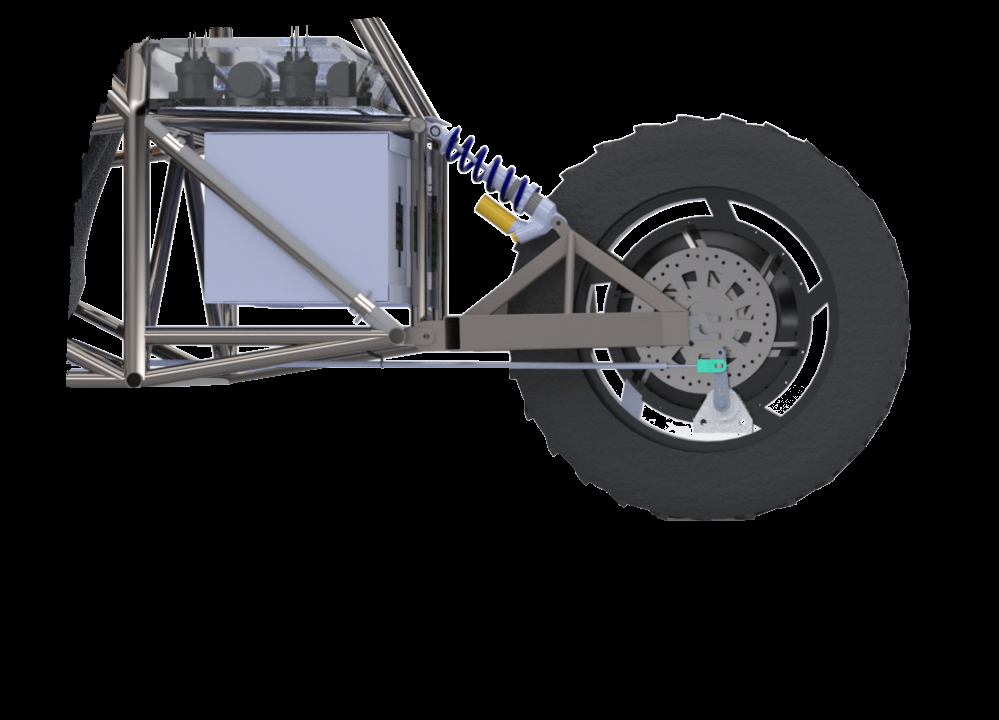
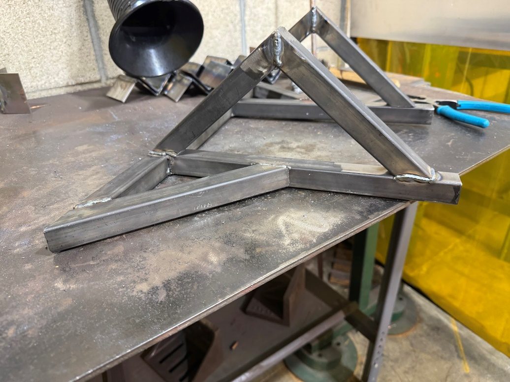
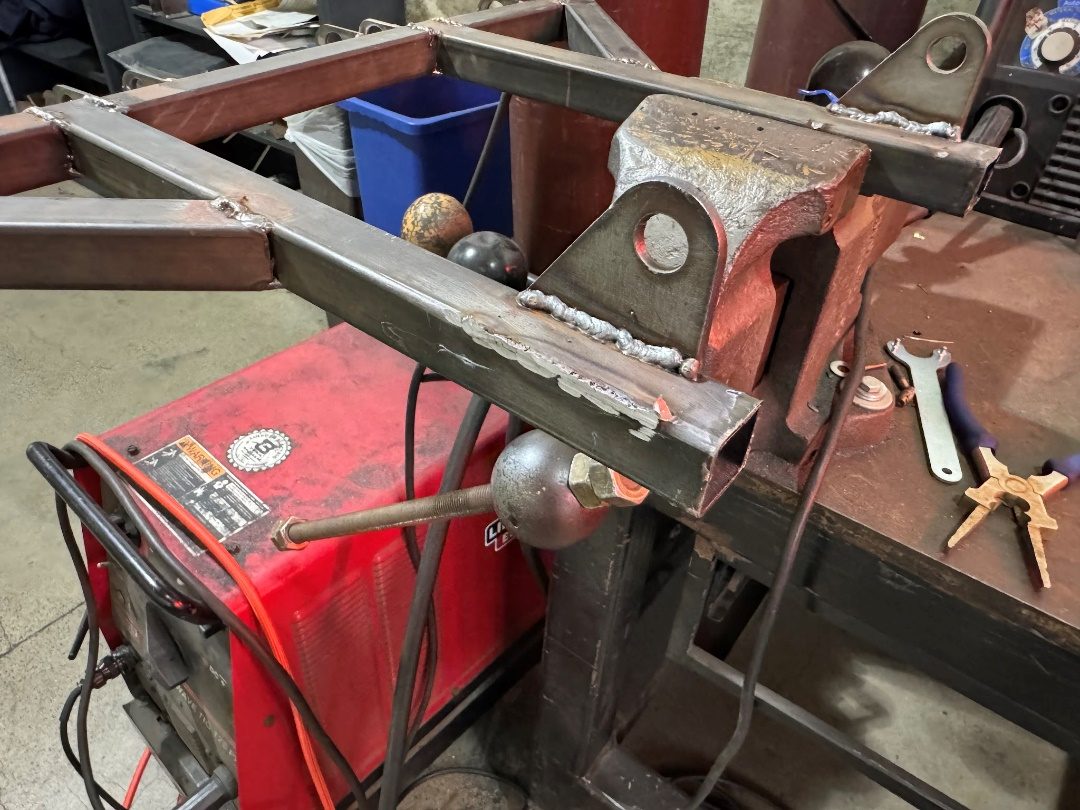
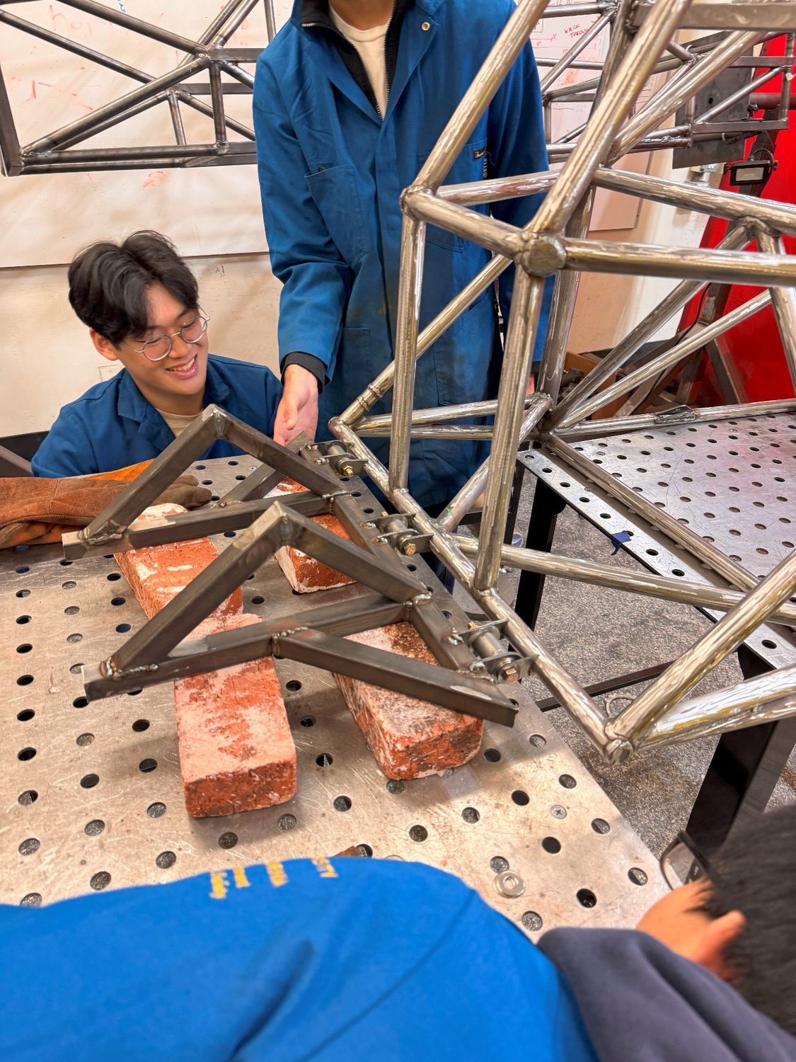
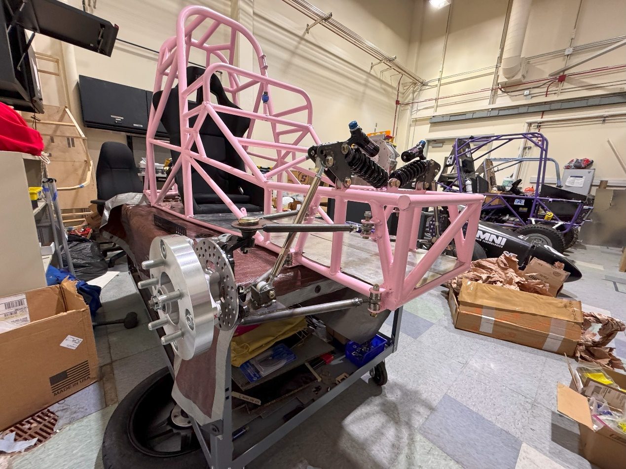
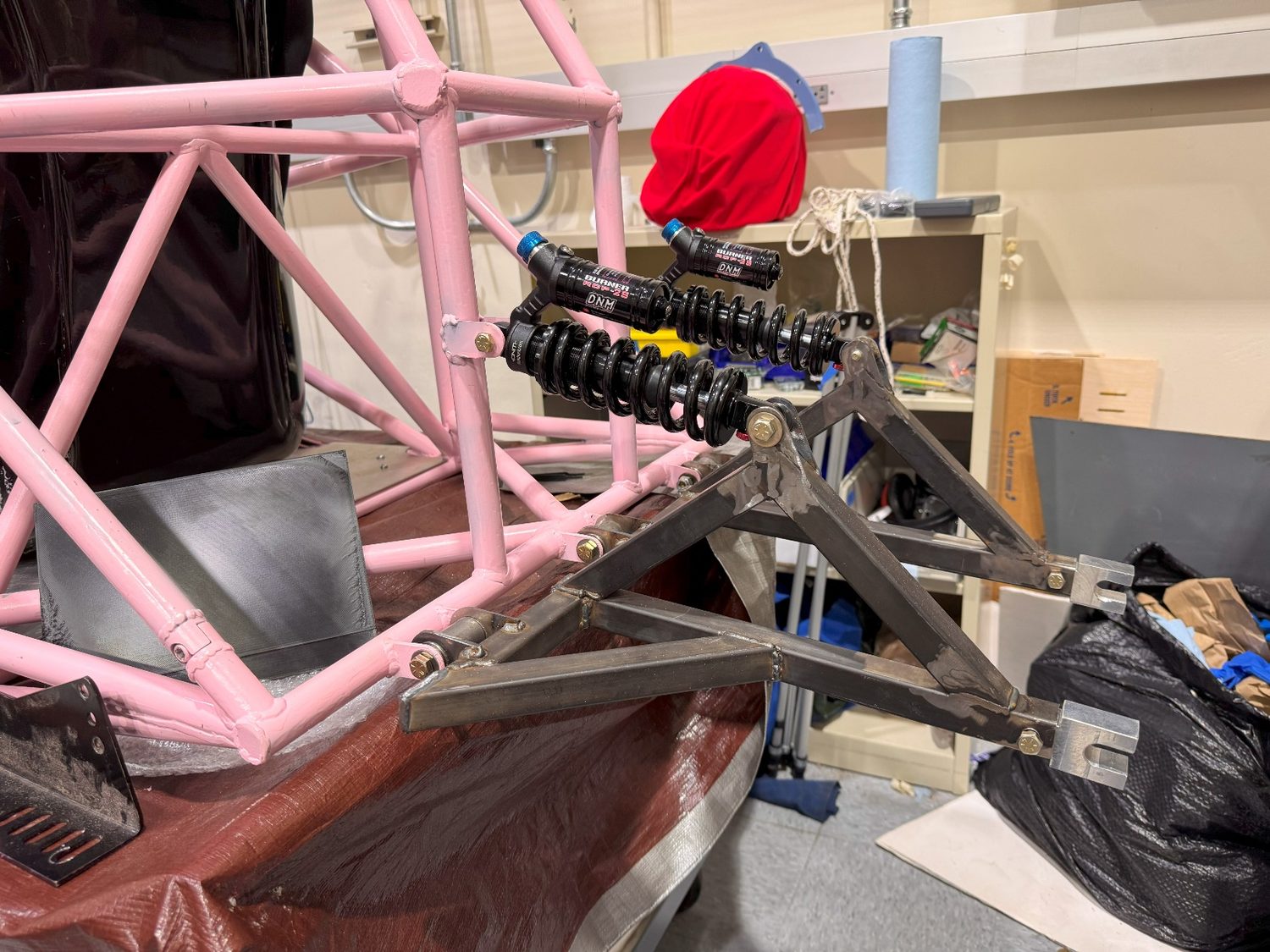
The rear trailing arm was carried over from the first-generation car. I ground the old mounting tabs off it and welded up the new members to finish the arm. As one of the few people on the subteam with welding experience, I then welded the front suspension tabs and the trailing arm onto the chassis while other members set the welding jigs. With the tabs and the arm on the chassis, both the front and rear suspension were ready to assemble.
Steering column supports
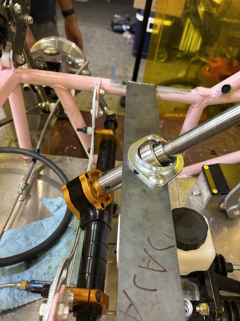
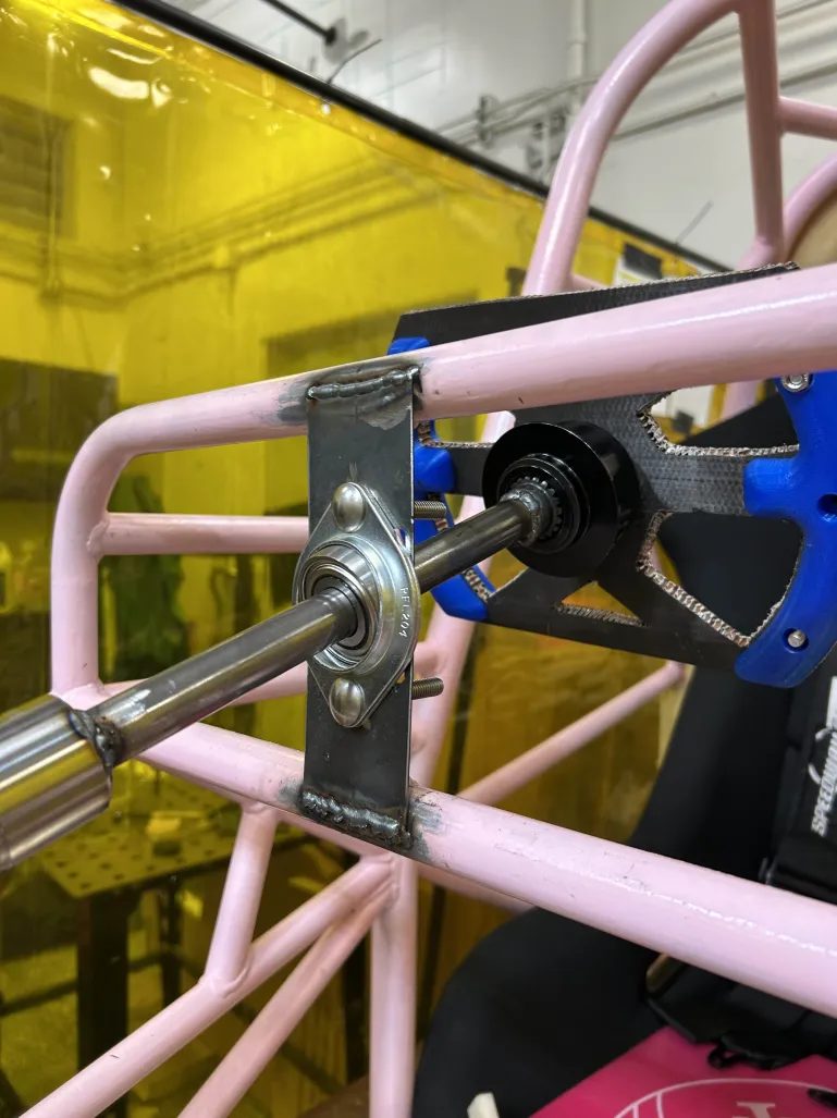
The steering column had to be rigidly supported and its travel positively limited for the car to pass technical inspection. I built the early iterations of the column supports: I cut the bearing collars at the machine shop, fitted the bearings, and welded them to tubes that were then welded to the chassis. When that arrangement did not fully take the play out of the column, I worked with the EV team on the fix that did, mounting flange bearings above the suspension box and behind the dashboard. That brought the column into compliance, made the car steerable, and completed the front suspension.
Building the rolling chassis
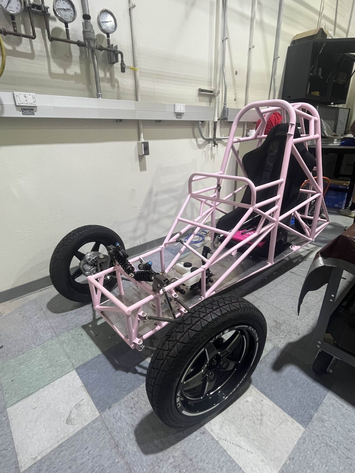
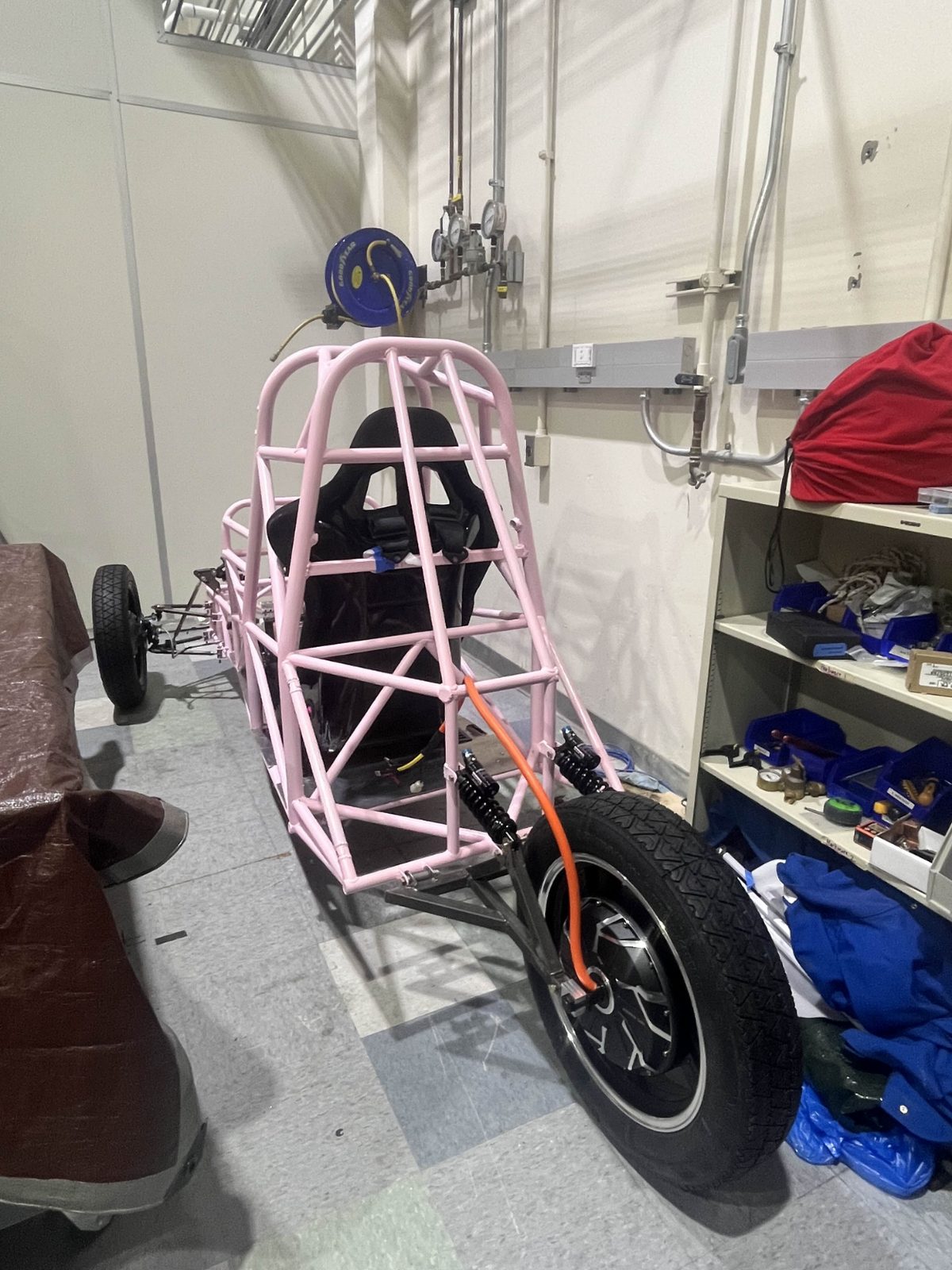
With the suspension welded up, I assembled the front and rear suspension, less the wheels, setting the front rod ends centered between their tabs. The whole subteam then set the front and rear ride height, mounted the major components, fitted the tires to the wheels, and lowered the car onto the ground as a rolling chassis, and then a powered chassis once the drivetrain was in. That was the milestone that let the other subteams start running dynamics tests.
Optimization: flange bushings
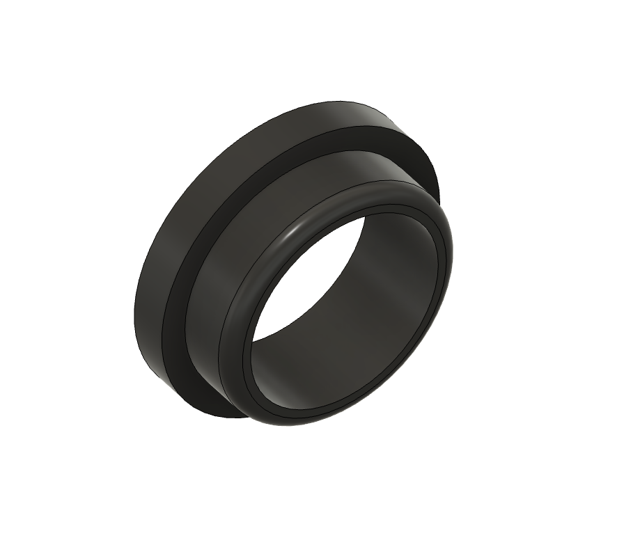
With the car assembled, I started tightening it up. Several suspension mounting holes were larger than the bolts running through them, which allowed slop at points where the geometry needs to be precise. I designed flange bushings to take up that clearance and printed them in carbon-fiber-reinforced nylon, bringing those joints in line with the regulations.