RC Rover
Design Report
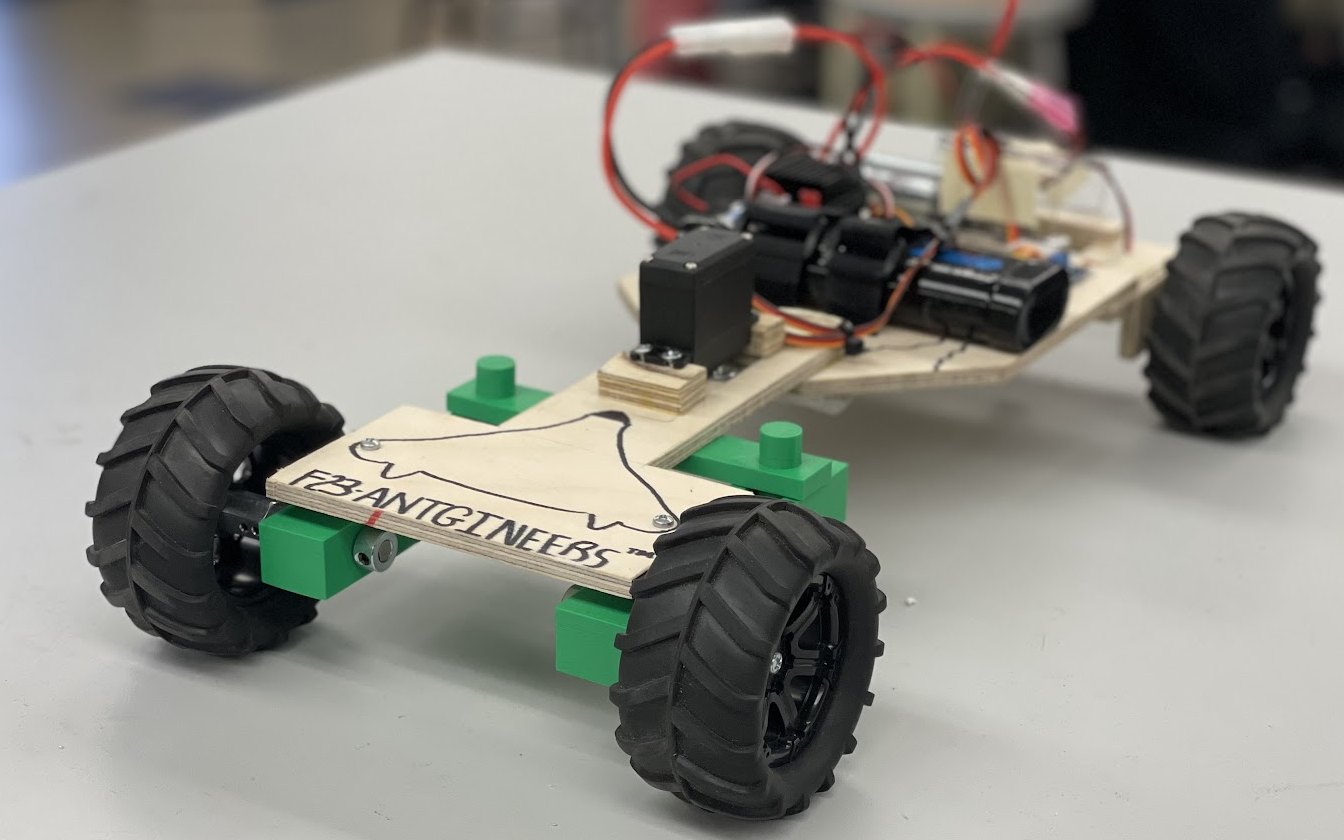
The Rover
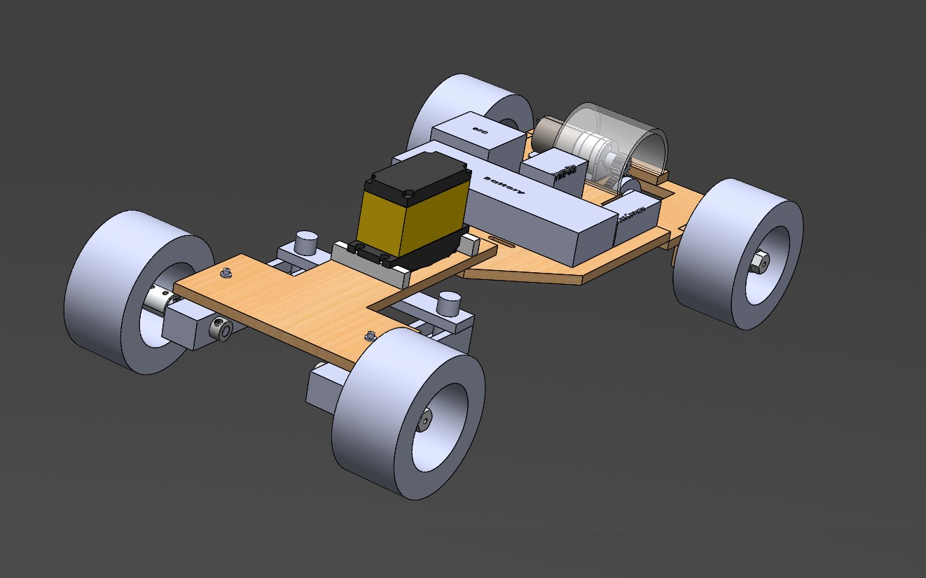
The final design of our rover is pictured above with its SolidWorks design pictured below. Our rover changed significantly from our preliminary designs to what we put on the track. Ultimately, our rover design was reduced down to three subassemblies, which we called: Rear Drive Train, Main Chassis, and Steering. The rover in its final form stands at 9.50 × 15.95 inches, putting us just below the dimensional constraint. It also satisfies safety requirements, as all edges were sanded down to ensure the safety of any user. Furthermore, to prevent accidents involving the gears in the Rear Drive Train, a gear guard was fabricated.
Using SolidWorks, we were able to find the center of gravity at ≅ 4.64 inches in the x-direction (width) and ≅ 6.81 inches in the y-direction (length), when the furthest back and furthest left corner (the back left wheel, by the buck converter) of the rover was mated as the origin of the assembly file. Having run some manual calculations using the masses of the various components of our rover, we concurred that the SolidWorks calculations were a good estimate of the actual center of mass. This comes to no surprise as the majority of our rover's weight is in the rear end due to our electronics configuration.
Design Choices
As a team, we made some design choices based on theoretical benefits. The most important of these included selecting the 85mm wheels for greater ground clearance on our rover, as well as the 52 tooth gear in order to sit in the perfect medium between torque and linear speed.
Steering
The goal of any steering mechanism is to transfer rotational motion from one source, into motion that turns two wheels. Our goal aimed for that, and more. Our steering design is as an Ackerman steering system, with a four-bar linkage design. The goal of an Ackerman steering system is to achieve a turn radius that does not involve sliding the wheels along the ground, unlike a parallel steering system. The parts that move and make up the steering are all 3D printed out of ABS plastic.
To achieve an Ackerman steering system, a T-shaped link connected to the servo, henceforth referred to as the “servo-link”, is needed to achieve uneven steering. The servo link would rotate and cause two other links that the wheels are attached to turn, henceforth referred to as “wheel links”. By the nature of the servo link's T-shape, and the nature of circular motion, this would cause uneven steering to occur. The servo link rotates on the tail end, and due to that, one side of the link becomes closer to the wheels, the point of revolution, as it rotates. Although, with this, it becomes hard to make adjustments to desired specifications as at any one point, there are three points of revolution in the steering system, each with various and fluctuating rates of change.
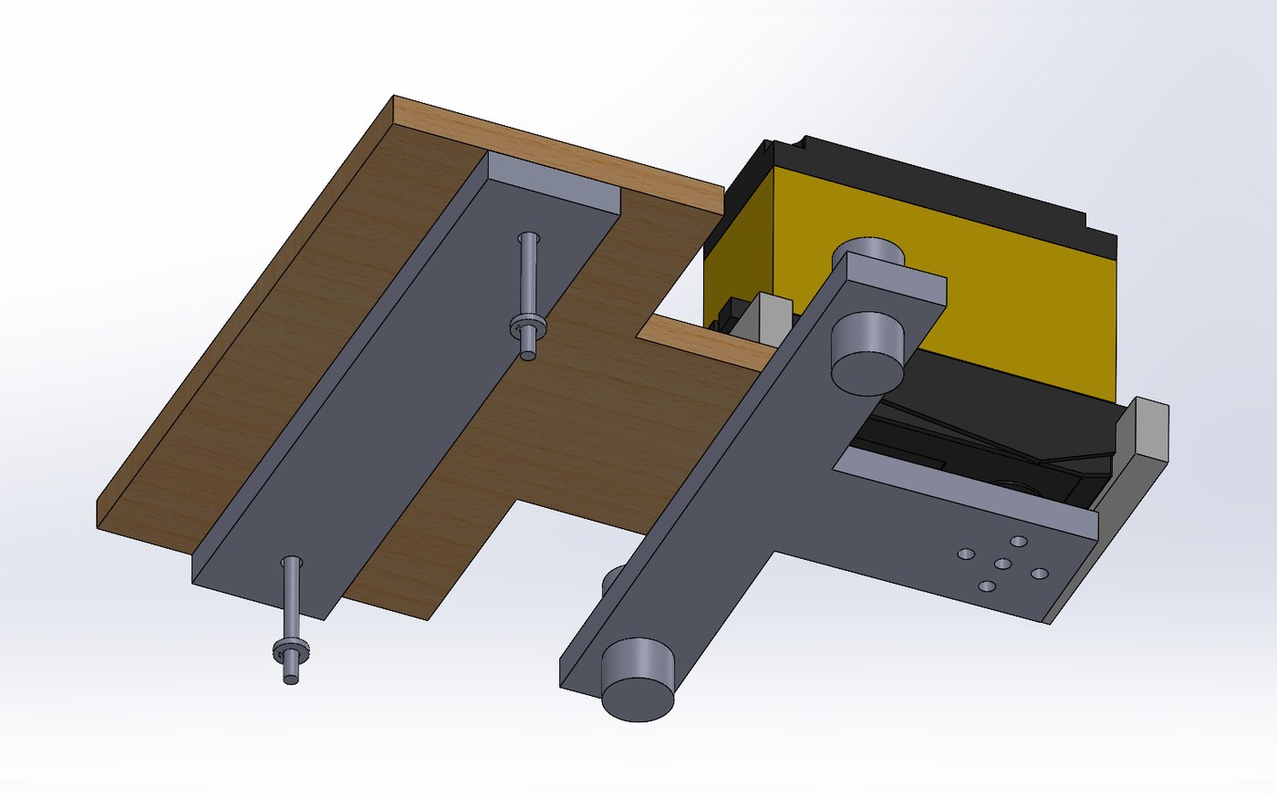
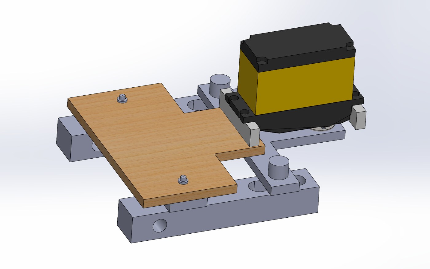
To assemble the steering, you must first screw in the servo link to the servo horn. There are five holes perfectly aligned to do the job, and you must orient the servo link with the horizontal part of the T facing forward. Next, a flat and straight link, dubbed the chassis link, aligns into the chassis holes all the way at the front end of the chassis extension. The chassis link only serves to be an anchor and a spacer for the wheel links. After the chassis link, and the wheel links are aligned to their respective left and right screw holes, where the wheel links are facing slot-side up, and the servo link is slotted in. Then you can begin screwing the wheel links to the chassis. After that is done, the steering system is complete, and all that is needed is the attachment of the wheels.